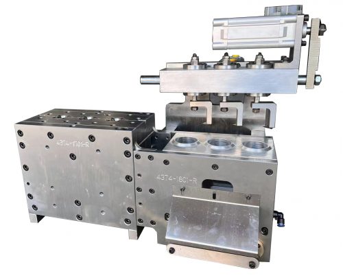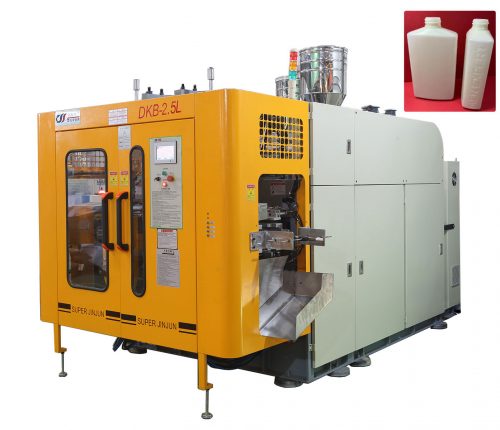
The extruder is a device consisting of mechanical and electrical components connected together. Residing within this combination of mechanical and electrical components is the screw or the heart of the extruder. These connected components support the heart. The extruder control is like our brain, it tells the rest of the extruder what to do using feedback from its various components. The extruder motor and gearbox can be compared to our legs and arms, they help get things done. However, without a heart, none of these bodily functions would work. If the extruder did not have the screw it couldn’t achieve its objective of melting a solid plastic into a flowable mass. This is not to discount the importance of the other components, but a poor performing screw or heart makes it difficult for the extruder to perform as expected. So what is the screw’s objective?
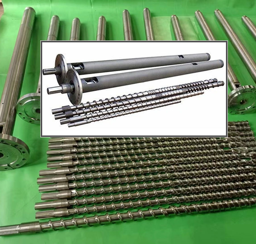
Extrusion screws on blow molding machine
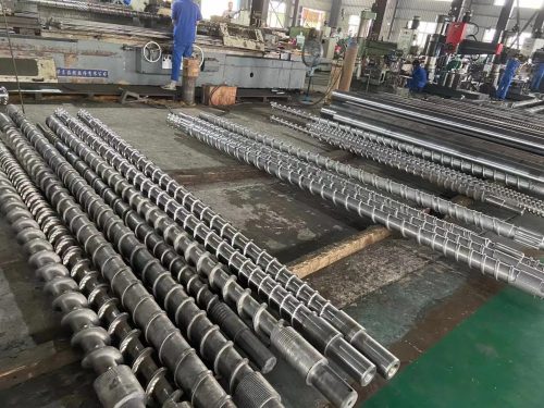
The screw is connected to the gearbox which is connected to an electric motor. The screw resides inside a barrel or cylinder which is encapsulated with heaters. As the screw rotates inside the barrel it takes energy from the electric motor and imparts into the plastic pellets causing them to melt. The screw has various geometric features which causes the plastic to transform. The plastic enters the extruder at a given temperature and it must be raised to a certain temperature to flow. This is achieved through shear and exposing the plastic to the heated barrel surface; the screw does all the work to the plastic.
All plastics have certain characteristics, a melting or softening point, specific heat, specific gravity to name a few. Each of these characteristics plays a part in the amount of energy required to process the plastic; but also the shape or geometry of the screw and extruder design. Let’s focus on the screw geometry or what we call the screw design.
Base on this reason, different extrusion screw if different plastic material. so there are special designed extrudion spindle (screw) as below:
HDPE extrusion screw
PVC extrusion screw
PC extrusion screw
PET extrusion screw
ABS extrusion screw
EVA extrusion screw
PA nylon extrusion screw
PMMA extrusion screw
1. Polycarbonate material
Features: Amorphous plastic with no obvious melting point, glass transition temperature 140 ~ 150, melting point 215 ~ 225, molding temperature 250 ~ 320.
High viscosity, sensitive to temperature, good thermal stability in the normal processing temperature range, basically does not decompose when staying at 300 for a long time, and begins to decompose when it exceeds 340, the viscosity is less affected by the shear rate.
Strong water absorption
Preferences:
In view of its good thermal stability and high viscosity, a. L/D try to choose a large aspect ratio to improve the plasticizing effect, the factory takes 26. Due to the wide melting temperature range and long compression time, the gradual change screw is used. L1=30% full length, L2=46% full length.
B. The compression ratio needs to be adapted to the melting rate from gradient A, but the melting rate cannot currently be calculated. According to the machinability of PC from 225 to 320, the gradient A value can be relatively upper middle. When L2 is large, ordinary gradient screw = 2 ~ 3, our factory = 2.6.
C. Due to its high viscosity and strong water absorption, a mixing structure is added on the screw before the homogenization section and after the compression section to strengthen the disintegration of the solid bed, and at the same time the entrained water can be converted into gas and escape.
D. Other parameters such as E, S, and the gap with the cylinder can be the same as other ordinary screws.
Ii. Plexiglass
Features: The glass transition temperature is 105, the melting temperature is above 160, the decomposition temperature is 270, and the molding temperature range is wide.
High viscosity, poor fluidity, good thermal stability.
Strong water absorption.
Preferences
A.L/D, choose a gradient screw with an aspect ratio of 20 ~ 22. According to the molding precision requirements of its products, L1=40%, L2=40%.
B. Compression ratio, generally 2.3 ~ 2.6.
c. Due to its certain hydrophilicity, the front end of the screw adopts a mixed ring structure.
d Other parameters can generally be designed according to the general screw, and the gap with the cylinder should not be too small.
3. PA (Nylon)
Features: There are many kinds of crystalline plastics with different melting points and narrow range of melting points. Generally, the melting point of PA66 is 260~265.
Low viscosity, good fluidity, obvious melting point, poor thermal stability.
Average water absorption.
Preferences
a, l/d, select a mutant screw with an aspect ratio of 18-20.
B. Compression ratio, generally 3 ~ 3.5, where H3=0.07 ~ 0.08 d is to prevent overheating and decomposition. Due to its low viscosity, the gap between the non-return ring and the barrel should be as small as possible, about 0.05, and the gap between the screw and the barrel should be about 0.08. If necessary, according to its material, the front end can be equipped with a non-return ring, and the nozzle should be self-locking.
d Other parameters can be designed according to the general screw.
4. Polyester fiber
Features: The melting point is 250 ~ 260, while the molding temperature of blown PET is wide, about 255 ~ 290.
Blow-molded PET has high viscosity, temperature has a great influence on viscosity, and poor thermal stability.
Preferences
l/d is generally taken as 20, L1=50%-55% and L2=20% in the three-stage distribution. The screw with low shear compression ratio is generally used, and the compression ratio is generally 1.8 ~ 2. Overheating due to shearing will cause discoloration or opacity H3=0.09 d
There is no mixing ring at the front end of the screw to prevent overheating and hiding materials.
Because this material is sensitive to temperature, manufacturers often use recycled materials. In order to increase production, our factory uses low-shear screws, so the motor speed can be appropriately increased to achieve the goal. At the same time, in the use of recycled materials (mostly plates), according to the actual situation, in order to increase the conveying capacity of the feeding section, the factory also adopted the method of increasing the diameter of the blanking material and opening grooves in the barrel, and achieved good results.
Heat-sensitive materials are generally divided into hard materials and soft materials. The difference lies in the amount of plasticizer added to the raw material, the hard one is less than 10%, and the soft one is more than 30%.
Features: no obvious melting point, softening at 60, viscoelasticity at 100 ~ 150, melting at 140, rapid decomposition at 170, softening point close to the decomposition point, decomposed and released in HC1 gas.
Poor thermal stability, temperature and time will cause decomposition, poor fluidity.
Design principles a. Strict temperature control, screw design as low shear as possible to prevent overheating.
B. The screw and barrel should be corrosion resistant.
C. The injection molding machine process should be strictly controlled.
Assuming the extruder is properly designed a significant amount of due diligence is required to properly specify and design a screw. An improperly specified or designed screw can make a really good machine design perform poorly.